
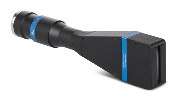
TC4K060-N – Opto Engineering Telecentric Lens
Request price quote
Request a quote for current pricing and stock on our B2B products — we respond the same day.
Telecentric lens for 4k line scan cameras, magnification 0.478x, mount M42x1 FD 10.56
Details
Technical Specifications
| Main optical specifications | ||
| Magnification | (x) | 0.478 |
| Image width | (mm) | 28.7 |
| Max sensor size | 4k | |
| Object field of view | ||
| Line 2k-5µm - 10.24 | (mm) | 21.42 |
| Line 2k-7µm - 14.34 | (mm) | 30.00 |
| Line 4k-5µm - 20.48 | (mm) | 42.85 |
| Line 4k-7µm - 28.67 | (mm) | 59.98 |
| Advanced optical specifications | ||
| Working distance (1) | (mm) | 174.0 |
| Working ƒ/N (2) | 16 | |
| Telecentricity typical (max) (3) | (deg) | < 0.06 (0.10) |
| Distortion typical (max) (4) | (%) | < 0.05 (0.08) |
| Depth of field (5) | (mm) | 7.40 |
| Resolution (6) | (μm) | 21 |
| Mechanical specifications | ||
| Mount (7) | M42x1 FD 10.56 | |
| Phase adjustment (8) | Yes | |
| Length (9) | (mm) | 355.3 |
| Width | (mm) | 83 |
| Height | (mm) | 52 |
| Mass | (g) | 1258 |
Last update 05 Sep 2023

Notes
- Working distance: distance between the front end of the mechanics and the object. Set this distance within ±3% of the nominal value for maximum resolution and minimum distortion.
- Working f-number (wf/N): the real f-number of a lens in operating conditions.
- Maximum angle between chief rays and optical axis on the object side. Typical (average production) values and maximum (guaranteed) values are listed.
- Percent deviation of the real image compared to an ideal, undistorted image. Typical (average production) values and maximum (guaranteed) values are listed.
- At the borders of the field depth the image can be still used for measurement but, to get a very sharp image, only half of the nominal field depth should be considered. Pixel size used for calculation is 7 μm.
- Object side, calculated with the Rayleigh criterion with λ= 520 nm
- FD stands for Flange Distance (in mm), defined as the distance from the mounting flange to the camera detector plane.
- Indicates the availability of an integrated camera phase adjustment feature.
- Measured from the front end of the mechanics to the camera flange.
Similar Products
You may also be interested in

Special Telecentric Series · Telecentric Lens
TCSE10M009-J – Opto Engineering Telecentric Lens
Request price quote
Special Telecentric Series · Telecentric Lens
TCSE16M024NIR-F – Opto Engineering Telecentric Lens
Request price quote
Special Telecentric Series · Telecentric Lens
TCSE16M024-F – Opto Engineering Telecentric Lens
Request price quote
Special Telecentric Series · Telecentric Lens
TCSE16M028VISNIR-F – Opto Engineering Telecentric Lens
Request price quoteRequest a Quote
Product: TC4K060-N – Opto Engineering Telecentric Lens