
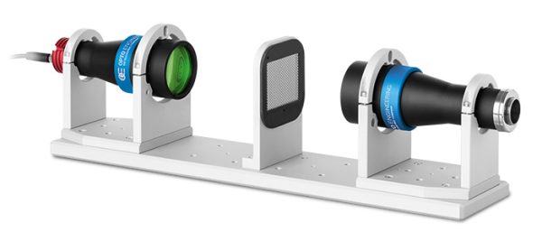
TCBENCH080 – Opto Engineering Telecentric Lens
Request price quote
Request a quote for current pricing and stock on our B2B products — we respond the same day.
Telecentric optical bench, magnification 0.110x
Details
Technical Specifications
| Main optical specifications | ||
| Magnification | (x) | 0.110 |
| Image circle diameter | (mm) | 11.0 |
| Max sensor size | 2/3″ | |
| Object field of view | ||
| 1/3” - 4.80 x 3.60 | (mm × mm) | 43.64 x 32.73 |
| 1/2.5” - 5.70 x 4.28 | (mm × mm) | 51.82 x 38.91 |
| 1/2” - 6.40 x 4.80 | (mm × mm) | 58.18 x 43.64 |
| 1/1.8” - 7.13 x 5.33 | (mm × mm) | 64.82 x 48.45 |
| 2/3” - 8.50 x 7.09 | (mm × mm) | 77.27 x 64.45 |
| Advanced optical specifications | ||
| Working distance (1) | (mm) | 226.8 |
| Working ƒ/N (2) | 8 | |
| Telecentricity typical (max) (3) | (deg) | < 0.04 (0.08) |
| Distortion typical (max) (4) | (%) | < 0.02 (0.10) |
| Depth of field (5) | (mm) | 34.20 |
| Resolution (6) | (μm) | 46 |
| Electrical specifications | ||
| Light color, peak wavelength | green, 520 nm | |
| Supply voltage | (V) | 12-24 |
| Max power consumption | (W) | 2.5 |
| LED voltage (7) | (V) | 2.8 (-) |
| LED current (8) | (mA) | 350 |
| Max pulse current (9) | (mA) | 2000 |
| Mechanical specifications | ||
| Mount | C | |
| Phase adjustment | No | |
| Length (10) | (mm) | 936 |
| Width | (mm) | 158 |
| Height | (mm) | 168 |
| Mass | (g) | 11150 |
| Environmental specifications | ||
| Operating temperature | (°C) | 0-40 |
| Storage temperature | (°C) | 0-50 |
| Operating relative humidity | (%) | 20-85, non condensing |
| Installation | Indoor use only | |
| Eye safety | ||
| Risk group according to CEI EN 62471:2010 | Exempt | |
Last update 22 Aug 2024


Notes
- Working distance: distance between the front end of the mechanics and the object. Set this distance within ± 3% of the nominal value for maximum resolution and minimum distortion.
- Working f-number (wf/N): the real f-number of a lens in operating conditions.
- Maximum angle between chief rays and optical axis on the object side. Typical (average production) values and maximum (guaranteed) values are listed.
- Percent deviation of the real image compared to an ideal, undistorted image. Typical (average production) values and maximum (guaranteed) values are listed.
- At the limits of the depth of field, the image can still be used for measurements. For a very sharp image, however, only half of the depth of field should be considered. Pixel size used for calculation is 3.45 μm.
- Object side, calculated with the Rayleigh criterion with λ= 520 nm
- At max forward current. Tolerance is ± 0.06V on forward voltage measurements.
- Used in continuous (not pulsed) mode.
- At pulse width <= 10 ms, duty cycle <= 10% condition. Built-in electronics board must be bypassed (see tech info).
- Measured from the camera flange of the objective lens to the electronic end of the illuminator. Cable, connector and mount thread excluded.
Similar Products
You may also be interested in

Special Telecentric Series · Telecentric Lens
TCSE10M009-J – Opto Engineering Telecentric Lens
Request price quote
Special Telecentric Series · Telecentric Lens
TCSE16M024NIR-F – Opto Engineering Telecentric Lens
Request price quote
Special Telecentric Series · Telecentric Lens
TCSE16M024-F – Opto Engineering Telecentric Lens
Request price quote
Special Telecentric Series · Telecentric Lens
TCSE16M028VISNIR-F – Opto Engineering Telecentric Lens
Request price quoteRequest a Quote
Product: TCBENCH080 – Opto Engineering Telecentric Lens